¡Tu solución está lista!
Nuestra ayuda de expertos desglosó tu problema en una solución confiable y fácil de entender.
Mira la respuestaMira la respuesta done loadingPregunta: Assume that the switches are periodically toggling between terminals 1 and 2. so that they spend 50 ms connected to terminal 1 and 50 ms connected to terminal 2. Draw the capacitor voltage and inductor
Assume that the switches are periodically toggling between terminals 1 and 2.
so that they spend 50 ms connected to terminal 1 and 50 ms connected to terminal
2. Draw the capacitor voltage and inductor current from t = 0 s to t = 300 ms,
if both the capacitor and the inductor are discharged and initially both
the switches are on 1.
Note: The requested voltage and current drawing may not be exact, but it should be correct
explained and drawn in an appropriate coordinate system Esta es la mejor manera de resolver el problema.Solución

Texto de la transcripción de la imagen:
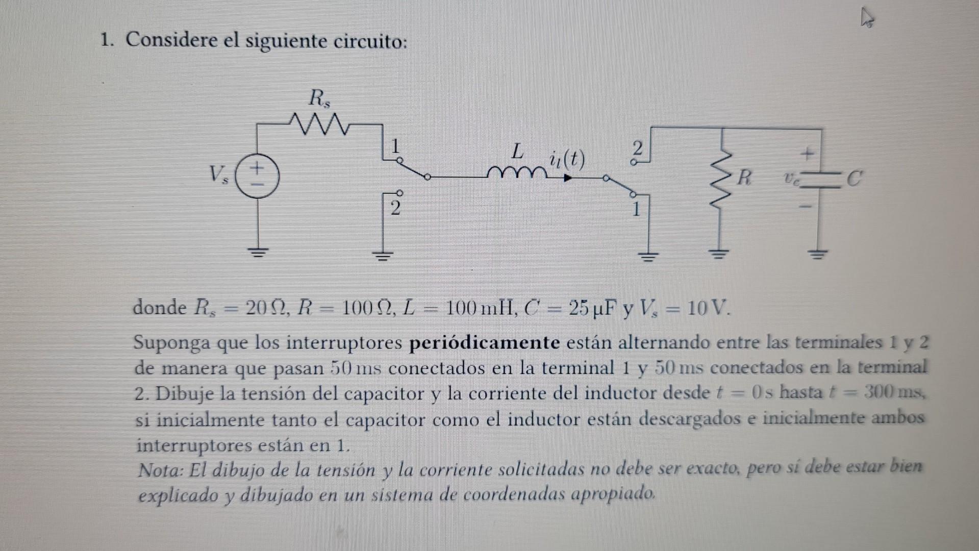
1. Considere el siguiente circuito: donde Rs=20Ω,R=100Ω,L=100mH,C=25μF y Vs=10 V. Suponga que los interruptores periódicamente están alternando entre las terminales 1 y 2 de manera que pasan 50 ms conectados en la terminal 1 y 50 ms conectados en la terminal 2. Dibuje la tensión del capacitor y la corriente del inductor desde t=0 s hasta t=300 ms, si inicialmente tanto el capacitor como el inductor están descargados e inicialmente ambos interruptores están en 1. Nota: El dibujo de la tensión y la corriente solicitadas no debe ser exacto, pero sí debe estar bien explicado y dibujado en un sistema de coordenadas apropiado.

Estudia mejor, ¡ahora en español!
Entiende todos los problemas con explicaciones al instante y pasos fáciles de aprender de la mano de expertos reales.