¡Tu solución está lista!
Nuestra ayuda de expertos desglosó tu problema en una solución confiable y fácil de entender.
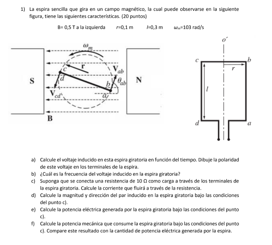
Mira la respuestaMira la respuesta done loadingPregunta: The single loop rotating in a magnetic field, which can be seen in the following figure, has the following characteristics. B= 0,5 T to the left r=0,1 m l=0,3 m ωm=103 rad/s a)
The single loop rotating in a magnetic field, which can be seen in the following figure, has the following characteristics.
B= 0,5 T to the left r=0,1 m l=0,3 m ωm=103 rad/s
a) Calculate the voltage induced in this rotating loop as a function of time. draw the polarity of this voltage at the terminals of the loop.
b) What is the frequency of the induced voltage in the rotating loop?
c) Suppose a 10 Ω resistor is connected as a load across the terminals of the rotating loop. Calculate the current that will flow through the resistor.
d) Calculate the magnitude and direction of the torque induced in the rotating loop under the conditions from point c).
e) Calculate the electrical power generated by the rotating loop under the conditions of the point c).
f) Calculate the mechanical power consumed by the rotating loop under the conditions of point c). Compare this result with the amount of electrical power generated by the loop.
 Esta es la mejor manera de resolver el problema.Solución
Please refe…
Mira la respuesta completa

Estudia mejor, ¡ahora en español!
Entiende todos los problemas con explicaciones al instante y pasos fáciles de aprender de la mano de expertos reales.