¡Tu solución está lista!
Nuestra ayuda de expertos desglosó tu problema en una solución confiable y fácil de entender.
Mira la respuestaMira la respuesta done loadingPregunta: Question 1 The state of stress at a point is displayed in the element. Determine a) the principal stresses, b) the maximum shear stress in the plane, c) the normal stress average and d) the angles of the stress planes main 𝜃𝑝 and maximum shear stress 𝜃𝑠. GRAPHIC SOLUTION Question 2 For purposes of analysis, a segment of a vehicle crankshaft is
Question 1
The state of stress at a point is displayed in the
element. Determine a) the principal stresses, b) the
maximum shear stress in the plane, c) the normal stress
average and d) the angles of the stress planes
main 𝜃𝑝 and maximum shear stress 𝜃𝑠.
GRAPHIC SOLUTION
Question 2
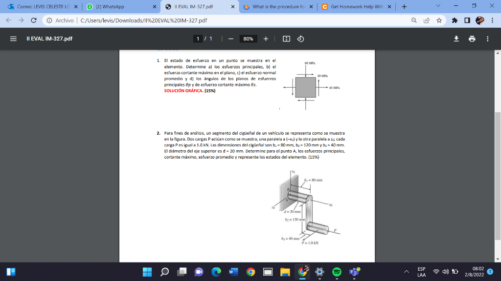
For purposes of analysis, a segment of a vehicle crankshaft is represented as shown
in the figure. Two charges P act as shown, one parallel to (–x0) and the other parallel to z0; each
load P is equal to 1.0 kN. The crankshaft dimensions are b1 = 80mm, b2 = 120mm and b3 = 40mm.
The diameter of the upper shaft is d = 20 mm. Determine for point A, the principal stresses,
maximum shear, average stress and represent the states of the element
 Esta es la mejor manera de resolver el problema.Solución100% (2 calificaciones)
(1). (2). I hope thi…
Mira la respuesta completa
Texto de la transcripción de la imagen:
1. El estado de esfuerzo en un punto se muestra en el elemento. Determine a) los esfuerzos principales, b) el esfuerzo cortante máximo en el plano, c) el esfuerzo normal promedio y d] los angulos de los planos de esfuerzos principales θp y de esfuerzo cortante máximo θs. SOLUCIÓN GRÁFICA. [15\%) 2. Para fines de análisis, un segmento del cigūeñal de un vehiculo se representa como se muestra en la figura. Dos cargas P actúan como se muestra, una paralela a (−xa) y la otra paralela a z∞; cada carga P es igual a 1.0kN. Las dimensiones del cigüeñal son b2=80 mm,b2=120 mmy b3=40 mm. El diámetro del eje superior es d=20 mm. Determine para el punto A, los esfuerzos principales, cortante máximo, esfuerzo promedio y represente los estados del elemento. (15\%)

Estudia mejor, ¡ahora en español!
Entiende todos los problemas con explicaciones al instante y pasos fáciles de aprender de la mano de expertos reales.