¡Tu solución está lista!
Nuestra ayuda de expertos desglosó tu problema en una solución confiable y fácil de entender.
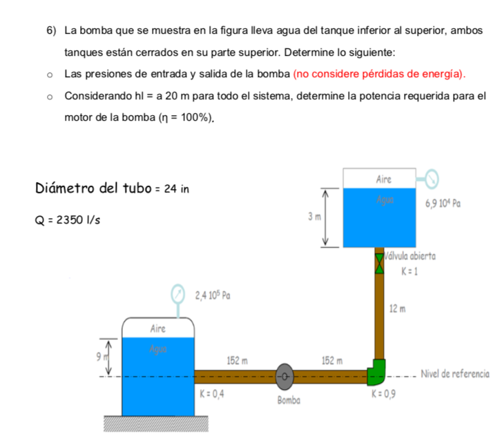
Mira la respuestaMira la respuesta done loadingPregunta: The pump shown in the figure takes water from the lower tank to the upper tank, both tanks are closed at the top. Determine the following: o The inlet and outlet pressures of the pump (energy losses are not considered). o Considering hl = a 20 m for the entire system, determine the power required for the pump motor (ƞ = 100%).
The pump shown in the figure takes water from the lower tank to the upper tank, both tanks are closed at the top. Determine the following:
o The inlet and outlet pressures of the pump (energy losses are not considered).
o Considering hl = a 20 m for the entire system, determine the power required for the pump motor (ƞ = 100%).
 Esta es la mejor manera de resolver el problema.SoluciónTe mostramos cómo abordar esta pregunta.
Este consejo generado con IA está basado en la solución completa de Chegg. ¡Regístrate para ver más!
To find the inlet and outlet pressures of the pump, use the Bernoulli equation between the inlet and outlet of the pump, taking into account the given flow rate and pipe diameter to calculate the velocity of the water in the pipe.


Estudia mejor, ¡ahora en español!
Entiende todos los problemas con explicaciones al instante y pasos fáciles de aprender de la mano de expertos reales.