Mechanical Engineering Archive: Questions from May 20, 2022
-
0 answers
-
1 answer
-
Determine the maximum and minimum axial stress in the beam shown in Figure 1. It has the section shown in Figure 2. W1= 2kip/ft; W2= 3 kip/ft y F1= 50 kip
Problema 1. Determinar el esfuerzo axial máximo y mínimo en la viga mostrada en la Figura 1. La misma tiene la sección mostrada en la Figura 2. W1 = 2 kip/ft; W2 = 3 kip/ft y F1 = 50 kip W₂ A Fig1 answer -
1 answer
-
0 answers
-
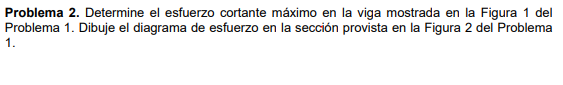
Determine the maximum shear stress in the beam shown in Figure 1. Draw the stress diagram at the section provided in Figure 2. W1= 2 kip/ft; W2= 3 kip/ft and F1= 50 kip.
Problema 2. Determine el esfuerzo cortante máximo en la viga mostrada en la Figura 1 del Problema 1. Dibuje el diagrama de esfuerzo en la sección provista en la Figura 2 del Problema 1. HUSSILL A F1 answer -
1 answer
-
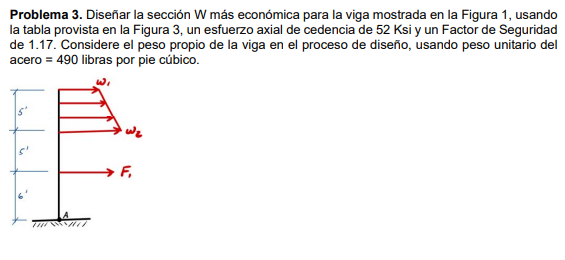
Design the most economical section W for the beam shown in Figure 1, using the table provided in Figure 3, an axial yield stress of 52 ksi, and a factor of safety of 1.17. Consider the self weight of
Problema 3. Diseñar la sección W más económica para la viga mostrada en la Figura 1, usando la tabla provista en la Figura 3, un esfuerzo axial de cedencia de 52 Ksi y un Factor de Seguridad de 1.1 answer -
Problem 1. Determine the maximum and minimum axial stress in the beam shown in Figure 1. It has the section shown in Figure 2. W1 = 2 kip/ft; W2 = 3 kip/ft and F1 = 50 kip
Problema 1. Determinar el esfuerzo axial máximo y mínimo en la viga mostrada en la Figura 1. La misma tiene la sección mostrada en la Figura 2. W1 = 2 kip/ft; W2 = 3 kip/ft y F1 = 50 kip F₁ TH A1 answer -
1 answer
-
Problem 2. Determine the maximum shear stress in the beam shown in Figure 1 of the Problem 1. Draw the stress diagram in the section provided in Figure 2 of Problem one
Problema 2. Determine el esfuerzo cortante máximo en la viga mostrada en la Figura 1 del Problema 1. Dibuje el diagrama de esfuerzo en la sección provista en la Figura 2 del Problema 1. s' 9 A Figu1 answer -
Problem 1. Determine the maximum and minimum axial stress in the beam shown in Figure 1. It has the section shown in Figure 2. W1 = 2 kip/ft; W2 = 3 kip/ft and F1 = 50 kip Problem 2. Determine the ma
Problema 1. Determinar el esfuerzo axial máximo y mínimo en la viga mostrada en la Figura 1. La misma tiene la sección mostrada en la Figura 2. W1 = 2 kip/ft; W2 = 3 kip/ft y F1 = 50 kip F₁ A Fig1 answer -
1 answer
-
Problem 3. Design the most economical W section for the beam shown in Figure 1, using the table provided in Figure 3, an axial yield stress of 52 Ksi and a Safety Factor of 1.17. Consider the self wei
Problema 3. Diseñar la sección W más económica para la viga mostrada en la Figura 1, usando la tabla provista en la Figura 3, un esfuerzo axial de cedencia de 52 Ksi y un Factor de Seguridad de 1.0 answers -
1 answer
-
1 answer
-
1 answer
-
1 answer