¡Tu solución está lista!
Nuestra ayuda de expertos desglosó tu problema en una solución confiable y fácil de entender.
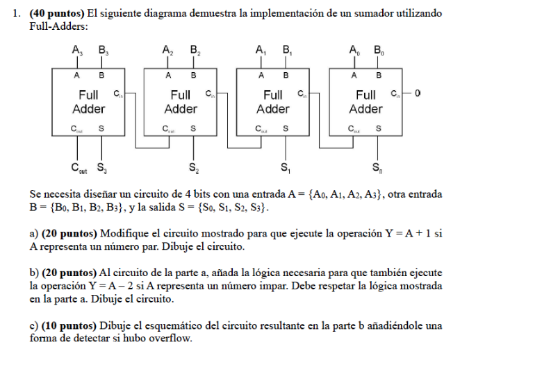
Mira la respuestaMira la respuesta done loadingPregunta: The following diagram shows the implementation of an adder using Full-Adders:A 4-bit circuit design is needed with one input A = {A₀, A₁, A₂, A₃}, another input B = {B₀, B₁, B₂, B₃}, and the output S = {S₀, S₁, S₂, S₃}.a)
The following diagram shows the implementation of an adder using Full-Adders:
A 4-bit circuit design is needed with one input A = {A₀, A₁, A₂, A₃}, another input B = {B₀, B₁, B₂, B₃}, and the output S = {S₀, S₁, S₂, S₃}.
a) Modify the displayed circuit to execute the operation Y = A + 1 if A represents an even number. Draw the circuit.
b) To the circuit from part a, add the necessary logic so it also executes the operation Y = A - 2 if A represents an odd number. You must respect the logic shown in part a. Draw the circuit.
c) Draw the schematic of the resulting circuit from part b, adding a way to detect if there was an overflow.
d) Using Tinkercad, assemble the circuit based on the designs and schematics from the previous parts. Provide a link or screenshot of your finalized design in Tinkercad.
 Hay 2 pasos para resolver este problema.SoluciónPaso 1Mira la respuesta completa
a) Modifying the circuit to execute the operation '
 DesbloqueaRespuestaDesbloquea

Estudia mejor, ¡ahora en español!
Entiende todos los problemas con explicaciones al instante y pasos fáciles de aprender de la mano de expertos reales.