¡Tu solución está lista!
Nuestra ayuda de expertos desglosó tu problema en una solución confiable y fácil de entender.
Mira la respuestaMira la respuesta done loadingPregunta: Figure 15.10 in the textbook describes an active bandpass filter. A) Find the transfer function of the system when Rf = 2 kΩ, Ri = 1 kΩ, RH = 82 kΩ, RL = 8.2 kΩ, and CL = CH = 1.2 nF. (12 points) B) Use Matlab or Octave to make the Bode plot of the voltage gain of this system.
Figure 15.10 in the textbook describes an active bandpass filter.
A) Find the transfer function of the system when Rf = 2 kΩ, Ri = 1 kΩ, RH = 82 kΩ, RL =
8.2 kΩ, and CL = CH = 1.2 nF. (12 points)
B) Use Matlab or Octave to make the Bode plot of the voltage gain of this system. Esta es la mejor manera de resolver el problema.SoluciónTe mostramos cómo abordar esta pregunta.
Este consejo generado con IA está basado en la solución completa de Chegg. ¡Regístrate para ver más!
Applying Kirchhoff's Current Law (KCL) at node involves summing up the currents going into the node and setting that equal to zero: .
SCRIPT FOR BODE PL…
Mira la respuesta completa
Texto de la transcripción de la imagen:
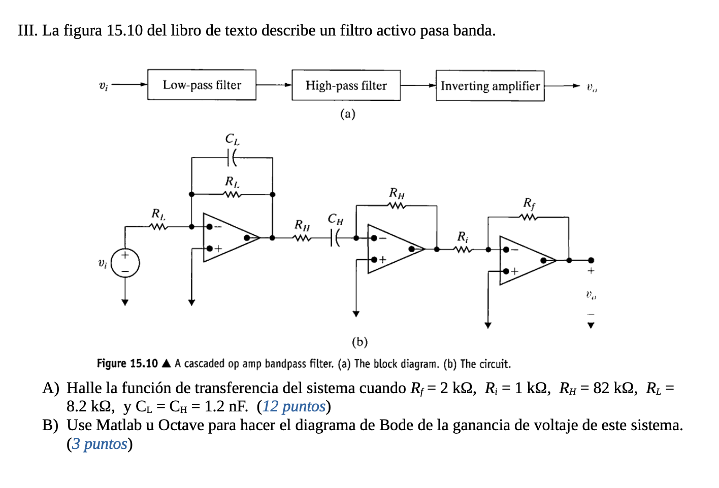
III. La figura 15.10 del libro de texto describe un filtro activo pasa banda. V; Low-pass filter High-pass filter Inverting amplifier U (a) CL HE R. RH R Ri w Ry Сн w6 R; + + vi + V = = = (b) Figure 15.10 A A cascaded op amp bandpass filter. (a) The block diagram. (b) The circuit. A) Halle la función de transferencia del sistema cuando R;= 2 k22, R; = 1 k92, Rw = 82 k92, R1 = 8.2 k2, y CL = CH = 1.2 nF. (12 puntos) B) Use Matlab u Octave para hacer el diagrama de Bode de la ganancia de voltaje de este sistema. (3 puntos) u

Estudia mejor, ¡ahora en español!
Entiende todos los problemas con explicaciones al instante y pasos fáciles de aprender de la mano de expertos reales.