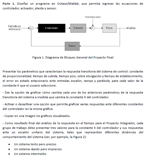
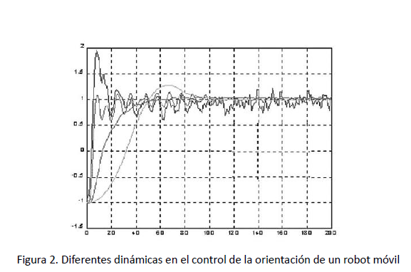
Electrical Engineering Archive: Questions from October 22, 2023
-
-3. Prove the following Fourier transform theorems: (a) \( \mathcal{F} \mathcal{F}\{g(x, y))=\mathcal{F}^{-1} \mathcal{F}^{-1}\{g(x, y))=g(-x,-y) \) at all points of continuity of \( g \). (b) \( \mat1 answer -
1 answer
-
1 answer
-
1 answer
-
a) Selecctonar un nodo de RAI. y plentear vadores - ecuaciones para los domas nodos \( \rightarrow \) Lucjo resuilse les ecuaciona resultenta. b) Plantia un Sistema de ec Malles 2 pronita Nescribir el1 answer -
1 answer
-
1 answer
-
1 answer
-
1 answer
-
Parte 1. Diseñar un programa en Octave/Matlab, que permita ingresar las ecuaciones de controlador, actuador, planta y sensor. Figura 1. Diagrama de Bloques General del Proyecto Final Presentar los pa0 answers -
Experimento 1: En el primer experimento se construyó el circuito que se muestra en la figura usando un diodo de silicio en serie con un resistor de \( R=34 \Omega \) y el voltaje de la fuente es \( V1 answer -
Usar las herramientas de Zoom In para obtener valores más precisos o seleccionar el área donde deseas hacer Zoom y si quieres regresar a los ajustes iniciales del gráfico presiona el icono de Home.1 answer -
A continuación se muestra una ser̃al de voltaje: Recuerda que puedes hacer zoom (rueda del ratón ¿Cuál es el voltaje máximo Vm? \[ V_{m}=\quad \mathrm{V} \] ¿Cuál es el voltaje pico pico Vpp?1 answer -
En el experimento transistores FET se utilizó un circuito integrado \( \mathrm{CD} 4007 \) para armar el circuito que se muestra \( R_{D}=2325 \Omega \) Importante: Ingrese sus respuestas en las unid0 answers -
La ecuación característica de la corriente \( I_{D} \) en la región de saturación es: \( I_{D}=\frac{K}{2}\left(V_{G S}-V_{t}\right)^{2}\left(1+\lambda V_{G S}\right) \) si \( \lambda \approx 0 y0 answers -
En el experimento transistores FET se utilizó un circuito integrado \( \mathrm{CD} 4007 \) para armar el circuito que se muestra \( R_{D}=2325 \Omega \) Importante: Ingrese sus respuestas en las unid0 answers -
En el experimento transistores BJT se utilizó un transistor PNP con una ganancia de corriente de \( \beta=100 \) para armar el circuito que se muestra en la figura, donde el voltaje del colector es \1 answer -
En el experimento transistores BJT se utilizó un transistor PNP con una ganancia de corriente de \( \beta=290 \) para armar el circuito que se muestra en la figura, donde el voltaje del colector es \1 answer -
1 answer
-
Utilice el método del Equivalente Thévenin para determinar la máxima transferencia de potencia a una carga colocada entre los puntos a y b.
En el circuito de la figura, utilice el método del equivalente thevenin para determinar la máxima transferencia de potencia a una carga colocada entre los puntos a-b1 answer -
1 answer
-
\( E_{j} \) Determine \( v_{0} \). Asumir que \( +V_{c c}=15 V \quad y-V_{c c}=-13 V \) para cado op-amp.1 answer -
The OP-AMP used is a 741 in a noisy environment. The noise level entering the op-amp is estimated to be 20 mV. Determine the signal and noise level at the output of the OP-AMP.
El OP-AMP usado es un 741 en un ambiente ruidoso. Se estima que el nivel de ruido que entra al op-amp es \( 20 \mathrm{mV} \). Determine el nivel de señal y de ruido en la salida del OP-AMP.1 answer -
1 answer
-
0 answers
-
1 answer
-
In the shown figure: • Find the current, voltage, and power for each resistor in the circuit. • The potential difference between A and B.
6. En la figura mostrada: - Halle la corriente, voltaje y potencia para cada resistencia del circuito. - La diferencia de potencial entre \( \mathbf{A} \) y \( \mathbf{B} \).1 answer -
Determine la función de carga en el capacitor para todo tiempo t y con ella obtenga la carga en el capacitor después de 0.2 segundos en un circuito \( L R C \) en serie formado por un inductor con \2 answers -
1 answer
-
Calcule los voltajes V1 y V2 para el circuito de la figura 15.128 en forma fasorial, utilice la regla del divisor de voltaje.
16. Calcule los voltajes \( \mathbf{V}_{1} \) y \( \mathbf{V}_{2} \) para el circuito de la figura 15.128 en forma fasorial, utilice la regla del divisor de voltaje. (a) FIGURA 15.128 Problema 16.1 answer -
Determina la serie de Fourier de \( f(x) \) en el intervalo referido. a) \( f(x)=\left\{\begin{array}{lr}0, & -\pi1 answer