Electrical Engineering Archive: Questions from May 05, 2022
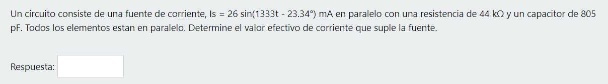
-
The impedance and propagation constant at 640 MHz for a transmission line are Zo = 58 + j2 Q and v=1 + j2 m-1 Determine the parameters per unit length of the line.
La impedancia y constante de propagación a 640 MHz para una línea de transmisión son Zo = 58 + j2 12 y y=1 + j2 m-? Determina los parámetros por unidad de largo de la línea. R R= L = G= CE1 answer -
An electromagnetic wave of 16.0 GHz has an electric field, E(z,t) y, with magnitude Eo = 50 V/m. If the wave propagates in the +z direction through a material with conductivity o = 3.3 x 10² S/m, rela
Una onda electromagnética de 16.0 GHz tiene un campo eléctrico, E(z,t) y, con magnitud E. = 50 V/m. Si la onda se propaga en la dirección de +z por un material con conductividad o = 3.3 x 10² S/m,1 answer -
1 answer
-
1 answer
-
Determine the magnitude of the voltage gain in (V/V)
Determina la magnitud de la ganancia de voltaje (VN). Asume que: • gm = 2.7 ms • RD = 3.5 k 2 • RL = 3.2 k2 +VDD Rp C3 V our O C RL Vin Ro Rs C2 MI =1 answer -
Determine the magnitude of the voltage gain in (V/V)
Determina la magnitud de la ganancia de voltaje (VN). Asume que: gm = 98.8 ms • RD = 133.9 k2 . RL = 1.4 k_2 +VDD RD C2 V out C w RL Vin RG =1 answer -
Determine the magnitude of the voltage gain in (V/V)
Determina la magnitud de la ganancia de voltaje (mVN). Asume que: = • gm = 43.1 ms • RD = 184.7 k2 • RL = 7.622 +VDD RD C3 RU Vout C 06 RL Vin w R2 Rs = HL = = =1 answer -
Determine the magnitude of the voltage gain in (mV/V)
Determina la magnitud de la ganancia de voltaje (mVN). Asume que: • gm = 7.0 ms • RS = 16 k12 • RL = 569.82 = +VDD C Vino C2 Vout RG w RS RL1 answer -
Determines the input resistance of the system (MΩ). Assume that:
Determina la resistencia de entrada del sistema (M.2). Asume que: • gm = 9.1 ms • RS = 14.1 k-2 = RL = 595.1 12 • RG = 12.5 M2 = +VDD C Vin C2 Vout RG Rs RL1 answer -
Determines the magnitude of the voltage gain (V/V). Assume that:
Determina la magnitud de la ganancia de voltaje (VN). Asume que: • gm = 4.3 ms • RD = 49.8 k 2 No se conecta ninguna carga +VDD RD C2 Vout RL w C. Vin RS1 answer -
Consider the following circuit, with C1=0.01F, V1=12V, I1=2A. After a long time of being the switches closed, At t=0 the switches OPEN, determine the equation of DISCHARGE, Vc(t) of the capacitor and
Considere el siguiente circuito, con C1=0.01F, V1=12V, 11=2A. Después de mucho tiempo de estar los interruptores cerrados, En t=0 en los interruptores se ABREN, determine la ecuación de DESCARGA, Vc1 answer -
The system in the figure is star-star. Find the phase voltages across the generator VAN, VBN, VCN(in phasor form). Determine the phase currents in the load IAN, IBN, ICN (in phasor form). Find the li
El sistema de la figura es de estrella-estrella. A. Encuentre los voltajes de fase en el generador VAN, VBN Y Ven (en forma fasorial). B. Determine las corrientes de fase en la carga Ian, Ibn y Icn (e1 answer -
For the ideal transformer in the figure, find: The currents I1, I2 and I0 (in phasor form) Voltages V1, V2 and V0 (in phasor form) The complex power delivered by the source.
Para el trasformador ideal de la figura encuentre: A. Las corrientes 11, 12 e 10 (en forma fasorial) B. Voltajes V1, V2 y Vo (en forma fasorial) C. La potencia compleja entregada por la fuente. 12 2 �1 answer -
For the system in the figure: Find the total average power, total reactive power, total apparent power, and total power factor. Find the current Is (in phasor form). If the loads can be modeled as a
Para el sistema de la figura: A. Encuentre la potencia promedio total, la potencia reactiva total, la potencia aparente total y el factor de potencia total. B. Encuentre la corriente Is (en forma faso1 answer -
1 answer
-
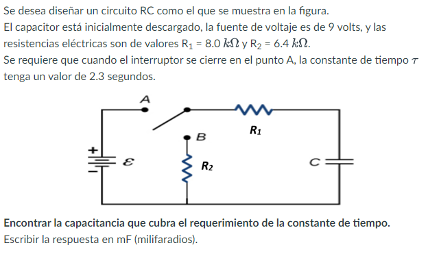
Consider the scenario of an RC circuit in the process of discharging, as shown in the figure, where the capacitor is initially fully charged and the switch is closed at point B. The voltage source i
Considere el escenario de un circuito RC en su proceso de descarga, como el que se muestra en la figura, en donde inicialmente el capacitor está completamente cargado y se procede a cerrar el interru1 answer -
1 answer
-
1 answer
-
1 answer
-
A 386 MHz flat wave with an electric field amplitude of 6 V / m propagating in the air affects a conductive plate normally (μr = 5.6, εr = 2.63, σ = 4.3x10⁴ S / m). Determine the skin depth within
Una onda plana de 386 MHz con amplitud de campo eléctrico de 6 V/m propagando en el aire incide normal en un plancha conductiva (up = 5.6, &r = 2.63, o = 4.3x10⁴ S/m). Determine el skin depth dentro1 answer -
1 answer
-
A 386 MHz flat wave with an electric field amplitude of 6 V / m propagating in the air affects a conductive plate normally (μr = 5.6, εr = 2.63, σ = 4.3x10⁴ S / m). Determine the skin depth within
Una onda plana de 386 MHz con amplitud de campo eléctrico de 6 V/m propagando en el aire incide normal en un plancha conductiva (Mr = 5.6, &r = 2.63, 0 = 4.3x10⁴ S/m). Determine el skin depth dentro1 answer -
The impedance and propagation constant at 649 MHz for a transmission line are Z0 = 80 + j1 Ω and γ = 2 + j6 m-1. Determines the parameters per unit length of the line.
La impedancia y constante de propagación a 649 MHz para una línea de transmisión son Zo = 80 + j1 2 yy=2 + j6 m-1. Determina los parámetros por unidad de largo de la línea. R= Q/m L = G = C =1 answer -
An electromagnetic wave of 2.8 GHz has an electric field, E(z,t) and, with magnitude E0 = 82 V/m. If the wave propagates in the direction of +z by a material with conductivity σ = 3.1 x 10⁻² S/m, rel
Una onda electromagnética de 2.8 GHz tiene un campo eléctrico, Ez,t) y, con magnitud EQ = 82 V/m. Si la onda se propaga en la dirección de +z por un material con conductividad o = 3.1 x 10⁻² S/m, p1 answer -
In a circuit we want to connect a 25 Ω source to a load of 150 Ω with a transmission line of 50 Ω. To achieve maximum power transfer, an inductor will be connected in series with the source. Determ
En un circuito deseamos conectar una fuente de 25 n a una carga de 150 con una linea de transmision de 50 12. Para lograr transferencia de potencia máxima se va a conectar un inductor en serie con la1 answer -
Use node voltage analysis to find the equation at node A of the following circuit. GIVEN: Vs = 150 cos(300t); R1 = 70Ω; R2 = 24Ω; R3 = 50Ω; C = 10 µF; L = 2H
Question 12 Time left 1:58:57 Usa análisis de voltaje de nodos para hallar la ecuación en el nodo A del siguiente circuito. Not yet answered С Marked out of L | A B HE m 1.0 I Remove flag + Vs im M1 answer -
1 answer
-
1 answer
-
Usa análisis de voltaje de nodos para hallar la ecuación en el nodo A del siguiente circuito.
A R1 w B Vsi M R2 w R3 Vs2 HI DADO: Vs4 = 225 cos(350t): Vs2 = 225 cos(350t); R1 = 50 0; R2 = 30 6: R3 = 100; C = 5 pF; L = 3 H Respuesta: VAI - V21 = +1 answer -
1 answer
-
1 answer
-
1 answer
-
1 answer
-
1 answer
-
1 answer
-
En un circuito deseamos conectar una fuente de 25Q a una carga de 150 Q con una linea de transmision de 50 0. Para lograr transferencia de potencia máxima se va a conectar un inductor en serie con la
En un circuito deseamos conectar una fuente de 25 ( a una carga de 150 con una linea de transmision de 50 n. Para lograr transferencia de potencia máxima se va a conectar un inductor en serie con la1 answer -
1 answer
-
An electromagnetic wave of 45.0 GHz has an electric field, E(z,t) y, with magnitude E0 = 64 V/m. If the wave propagates in the +z direction through a material with conductivity σ = 5.3 x 10^1 S/m, re
Una onda electromagnética de 45.0 GHz tiene un campo eléctrico, E(z,t) y, con magnitud Ep = 64 V/m. Si la onda se propaga en la dirección de +z por un material con conductividad o = 5.3 x 10's/m, p1 answer -
Given the voltage gain G(s) of the following systems: • Make the Bode plot using Matlab or Octave • Approximate the approximate Bode plot with line segments on the given curve by Matlab or Octave
I. Dado la ganancia de voltaje G(s) de los siguientes sistemas: Hacer el diagrama de Bode usando Matlab u Octave • Aproximar el diagrama de Bode aproximado con segmentos lineales sobre la curva entr0 answers -
II. Given the Bode diagram, determine the transfer function. -The diagrams in the image *Green lines are for guidance. Approximate Bode is red. The Bode given by Octave is blue in regions where the ap
II. Dado el diagrama de Bode, determinar la función de transferencia. Bode Diagram 26 G1 6 Magnitude [dB] -20 -40 -60 -80 -100 101 10° 10 102 -90 - 100 -135 -150 G1 Phase (deg] -200 - 2257 -250 2901 answer