Electrical Engineering Archive: Questions from March 31, 2022
-
1 answer
-
1 answer
-
PLEASE ANSWER FAST AND GOOD
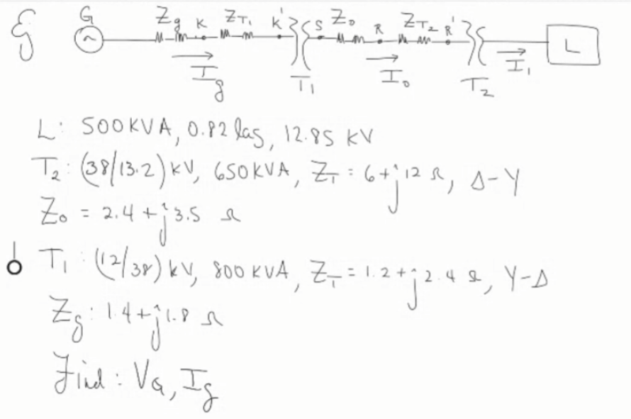
مهمة 6 ZTzR MMMM. R HAN 38 工。 Tz 2 Zg k Zr, kacs Zo 퀴 - 3 Li 500kVA, 0.82 lag, 12.85 kV Te: (38/13.2) KV, 650 KVA, Z, : 6+ 128, 5-Y Zo = 2,4+ 13.5 o T (2/3») ky, 800 KVA, Z7 = 1.2+72.44, Y-1 answer -
0 answers
-
0 answers
-
0 answers
-
0 answers
-
0 answers
-
1 answer
-
3) Determine the load on the 8μF capacitor if the Source is 15v.
3) Determine la carga en el capacitor de 8uF si la Fuente es de 15v. 1.5 uF 5.0 uF 8.0 uF 3.5 uF I 0.75 uF 15 ur1 answer -
1 answer
-
1 answer
-
1 answer
-
1 answer
-
1 answer
-
1 answer
-
1 answer
-
1 answer
-
0 answers