Electrical Engineering Archive: Questions from March 24, 2022
-
1 answer
-
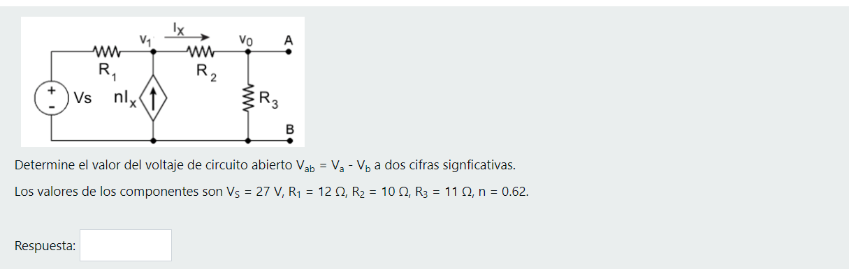
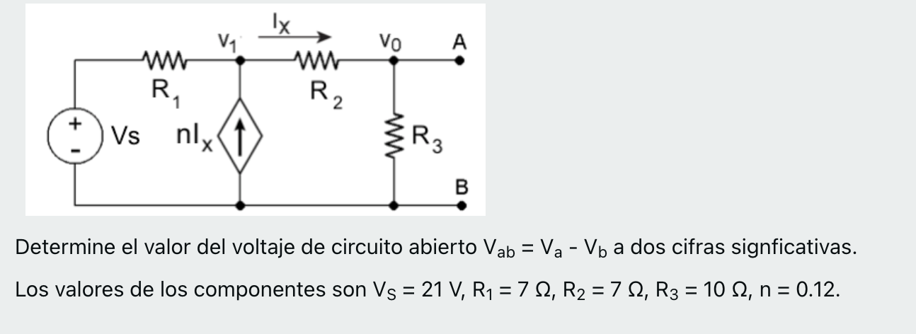
Determine the value of the open-circuit voltage Vab = Va - Vb to two significant figures. The component values are VS = 29 V, R1 = 15 Ω, R2 = 11 Ω, R3 = 12 Ω, n = 0.37.
vo A w Ix w R. 2. R Vs nlx R2 B Determine el valor del voltaje de circuito abierto Vab = Va - Vb a dos cifras signficativas. Los valores de los componentes son Vs = 29 V, R1 = 1512, R2 = 1112, R3 = 121 answer -
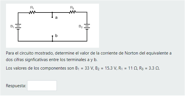
For the circuit shown, determine the value of the Norton current to the equivalent of two significant figures between terminals a and b. The component values are B1 = 19 V, B2 = 10.3 V, R1 = 11 Ω, R3
R. RE w a B B2 Para el circuito mostrado, determine el valor de la corriente de Norton del equivalente a dos cifras signficativas entre los terminales a y b. Los valores de los componentes son By = 191 answer -
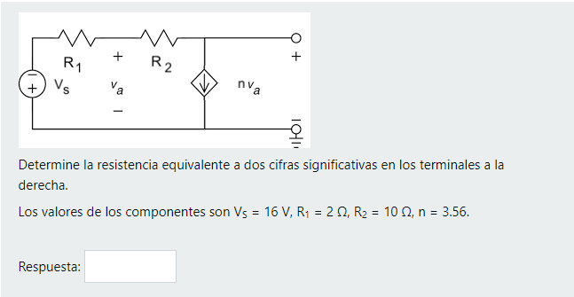
Determine the equivalent resistance to two significant figures at the terminals to the right. The component values are VS = 10 V, R1 = 7 Ω, R2 = 6 Ω, n = 4.64.
Mm +O + R2 R1 + Vs Va nva 101 Determine la resistencia equivalente a dos cifras significativas en los terminales a la derecha. Los valores de los componentes son Vs = 10 V, R2 = 72, R2 = 622, n = 4.641 answer -
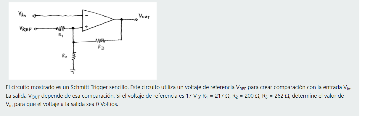
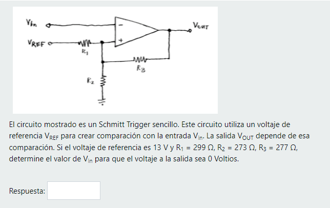
The circuit shown is a simple Schmitt Trigger. This circuit uses a reference voltage VREF to create comparison with the input Vin. The output VOUT depends on that comparison. If the reference voltage
Vbn a Veur VREF R w R3 R2 El circuito mostrado es un Schmitt Trigger sencillo. Este circuito utiliza un voltaje de referencia VREF para crear comparación con la entrada Vin. La salida Vout depende de1 answer -
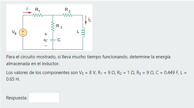
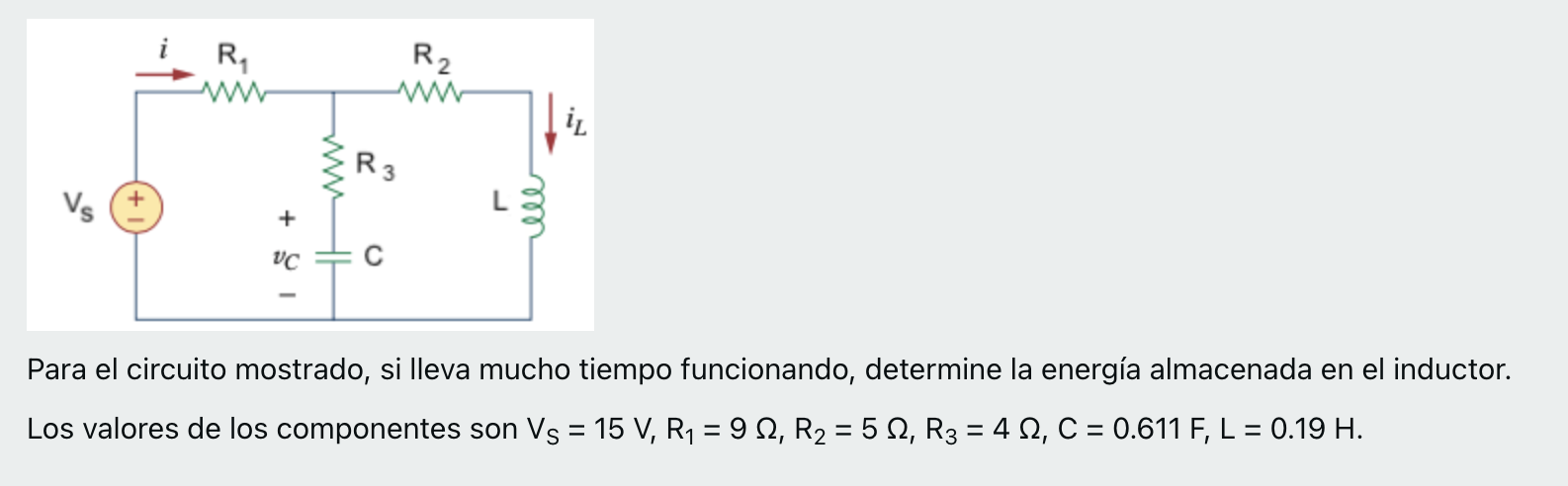
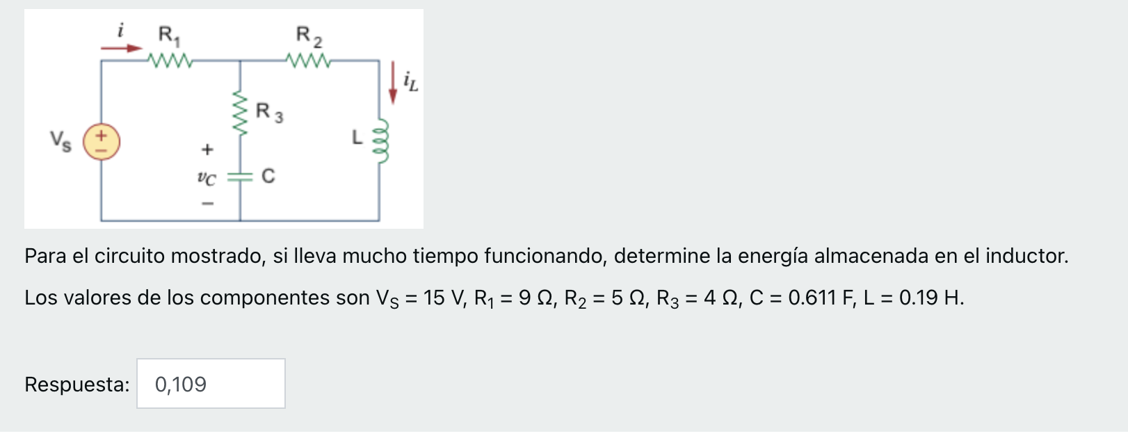
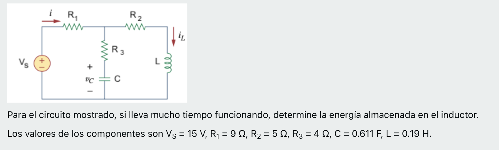
For the circuit shown, if it has been running for a long time, determine the energy stored in the inductor. The component values are VS = 8 V, R1 = 1 Ω, R2 = 8 Ω, R3 = 9 Ω, C = 0.739 F, L = 0.02 H.
R ww R2 w IL R3 ell VC с Para el circuito mostrado, si lleva mucho tiempo funcionando, determine la energía almacenada en el inductor. Los valores de los componentes son Vs = 8 V, R1 = 122, R2 = 8 11 answer -
1 answer
-
1 answer
-
1 answer
-
1 answer
-
1 answer
-
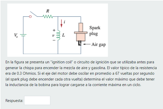
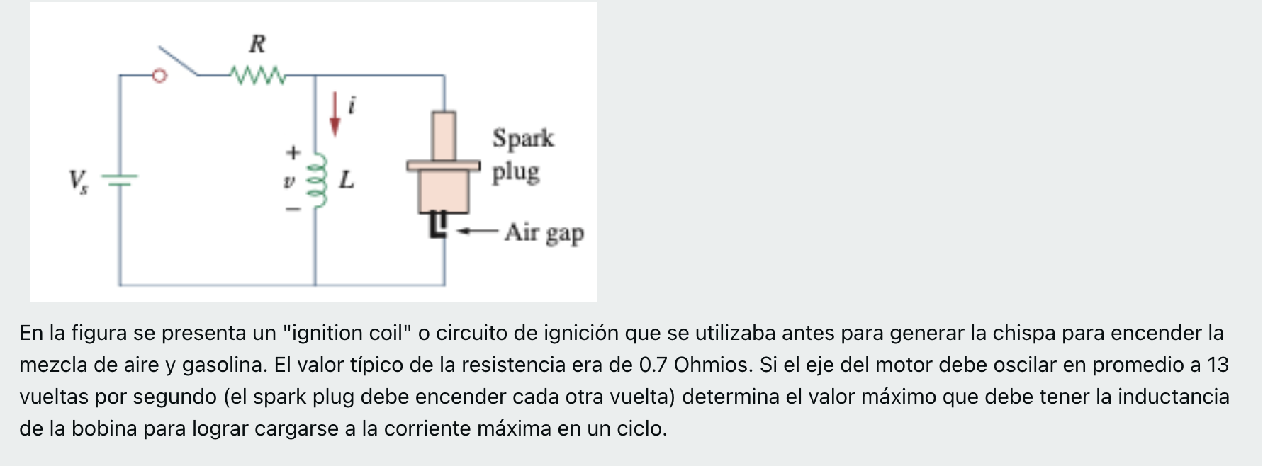
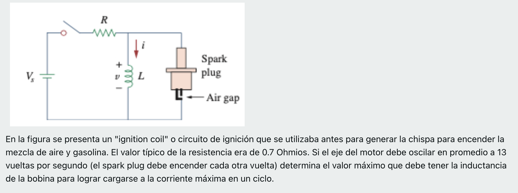
The figure shows an "ignition coil" ignition circuit that was previously used to generate the spark to ignite the mixture of air and gasoline, The typical value of the resistance was 0.3 ohms. If the
R Spark plug V. - Air gap En la figura se presenta un "ignition coilo circuito de ignición que se utilizaba antes para generar la chispa para encender la mezcla de aire y gasolina, El valor tipico de1 answer -
1 answer
-
1 answer
-
1 answer
-
1 answer
-
1 answer
-
1 answer
-
1 answer
-
0 answers
-
1 answer
-
Translation: Determine the value of the open-circuit voltage Vab = Va - Vb to two significant figures. The component values are VS = 15 V, R1 = 11 Ω, R2 = 15 Ω, R3 = 13 Ω, n = 0.63.
V1 Ix ww VO А w R. R2 Vs nlx R3 w B = Determine el valor del voltaje de circuito abierto Vab = V2 - Vo a dos cifras signficativas. Los valores de los componentes son Vs = 15 V, R4 = 11 12, R2 = 15 121 answer -
1 answer
-
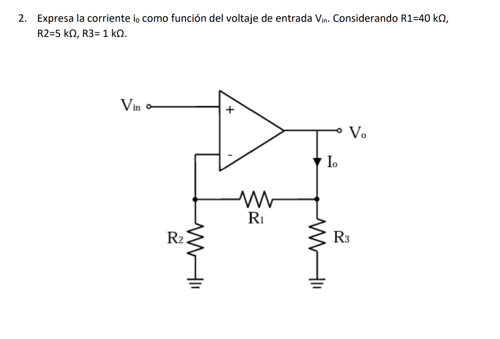
Obtén, Vo en función Vin, R1=2 Ω, R2=1 Ω, R3= 7 Ω, Vs= 4 V.
3. Obtén, Vo en función Vin, R1=2 12, R2=1 12, R3= 7 N, Vs= 4 V. R2 w Ri Vino w V. + Vs R31 answer -
1 answer
-
1 answer
-
1 answer
-
1 answer
-
1 answer
-
1 answer
-
1 answer
-
1 answer
-
1 answer
-
Obtener, Vo en función Vin, R1=2 Ω, R2=1 Ω, R3= 7 Ω, Vs= 4 V
3. Obtén, Vo en función Vin, R1=2 12, R2=1 12, R3= 7 N, Vs= 4 V. R2 w Ri Vino w V. + Vs R31 answer -
Determine el los voltejes de salida Vo1 y Vo2 en términos del voltaje de salida. Considere R1= 200 kΩ, R2= 40 kΩ, R3= 240 kΩ
4. Determine el los voltejes de salida Vol y Voz en términos del voltaje de salida. Considere R1= 200 k1, R2= 40 kN, R3= 240 k. Vin - Vol RI R2 R3 V21 answer -
1 answer
-
From the following circuit find the value of the current Io, using the superposition method
Del siguiente circuito encuentre el valor de la corriente Io, utilizando el método de superposición 6 ΚΩ W 2k1 W- 6k 8 mA 3k 1 ΚΩ 4 mA 12 V (+1 answer -
From the following circuit find the terminals A B: Thevenin resistance, Thevenin voltage, Norton current, Maximum power transfer in RL and what would be its value? What would be the power in the load
Del siguiente circuito encuentre entre los terminales A B: a- Resistencia de Thevennin 10 ptos b- Voltaje de Thevenin 15 ptos C- Corriente de Norton d- Máxima transferencia de potencia en RL y cual s1 answer -
In the figure we see a current segment along the x-axis from x = 0 to xL = 2.5 m with a current I of 2.5 A. Determine the magnitude of the magnetic field strength to two significant figures at point P
Pregunta 5 Sin responder aún Puntúa como 1.00 Marcar pregunta Р y. 1 +-> X X Ο Ι En la figura vemos un segmento de corriente a lo largo del eje de x desde x = 0 hasta XL = 2.5 m con una corriente1 answer -
Don't copy chegg answer values change please check the question and slove I give 2 upvotes I post 2nd time. In the figure we see a current segment along the x-axis from x = 0 to xL = 2.5 m with a curr
Pregunta 5 Sin responder aún Puntúa como 1.00 P Marcar pregunta Р y + - I +> X X 0 I En la figura vemos un segmento de corriente a lo largo del eje de x desde x = 0 hasta xL = 2.5 m con una corrien1 answer -
We wish to determine the voltage induced in the conductive triangle with angle θ = 51° due to the magnetic field B = 0.27 T az. The vertical segment shown at Xo is moving to the right at a speed u =
Pregunta 12 Sin responder aún Puntúa como 1.00 P Marcar pregunta o 0 В 0 osu 7x x Deseamos determinar el voltaje inducido en el triangulo conductivo con ángulo e = 51° debido al campo magnetico B1 answer -
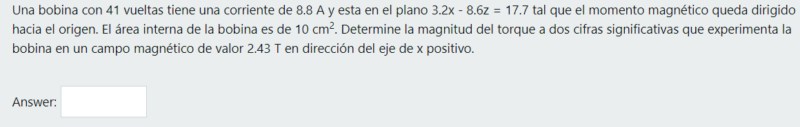
A coil with 87 turns has a current of 2.8 A and is in the 4.6x - 8.8z = 21.4 plane such that the magnetic moment is directed towards the origin. The internal area of the coil is 11.1 cm2. Determ
Pregunta 2 Sin responder aún Puntúa como 1.00 P Marcar pregunta Una bobina con 87 vueltas tiene una corriente de 2.8 A y esta en el plano 4.6x - 8.8z = 21.4 tal que el momento magnético queda dirig1 answer -
Find the Voltage V1 Find the Current I4 Find Es
Find the voltage V1. Vi 1 0.5A 2012 Rz R RA + R 3092 I 5V Es1 answer -
1 answer
-
1 answer
-
1 answer
-
1 answer
-
1 answer
-
1 answer
-
1 answer
-
Determine V0 using Thévenin's theorem.
4. Determine Vo utilizando el teorema de Thévenin. 4 ΚΩ V 3 mA 2 ΚΩ 4 ΚΩ 12 kΩ + 2 ΚΩ T 6V 1 mA1 answer -
1 answer
-
1 answer
-
1 answer
-
1 answer
-
In the figure shown there is an infinite line with a current, I = 5.8A, flowing in the direction of az. At a distance, d = 2.2cm, there is a rectangular box a * b, a = 3.4cm, b = 4.6cm. Determine the
z I b d En la figura mostrada hay una línea infinita con una corriente, 1 = 5.8 A, fluyendo en la dirección de az. A una distancia, d = 2.2 cm, se encuentra una caja rectangular a xb, a = 3.4 cm, b1 answer -
1 answer