Electrical Engineering Archive: Questions from March 18, 2022
-
Me podrían ayudar con este ejercicio.
Un sistema LTI de tiempo discreto está descrito por la ecuación: y(n) – žy(n − 1) + žy(n − 2) = f(n) donde 2(n): la entrada del sistema y(n) : salida del sistema determine: a) b) La función1 answer -
Alguien podría ayudarme con este ejercicio.
La envolvente compleja de una señal AM es: g(t) = Ac(1+ m(t)) La forma de la señal AM obtenida es: s(t) = g(t)cos(wet), donde we = 2nfc Esta señal s(t) ingresa a un BPF cuya respuesta en frecuencia1 answer -
Alguien me podría ayudar con este ejercicio.
Sea el sistema mostrado en la figura: X(s) Y(s) 1 s + 1 s +3 a) Obtenga la función de transferencia del sistema (detalle paso a paso, sin utilizar simplificación de bloques) b) Dibuje el diagrama de1 answer -
Alguien me ayuda con ese ejercicio
Considere un filtro ideal LPF con respuesta en frecuencia: H(w) = {. ) \WI < 411 || > Art La entrada a este filtro es la señal x(t) = e-2t u(t) a) Grafique H(W) b) Encuentre X(w) c) Grafique X(w) d)1 answer -
1 answer
-
1 answer
-
1 answer
-
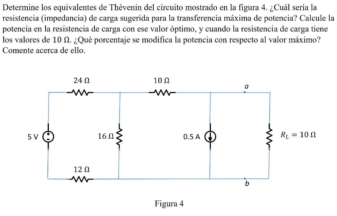
Determine the Thévenin equivalents of the circuit shown in Figure 4. What would be the suggested load resistance (impedance) for maximum power transfer? Calculate the power into the load resistor wit
Determine los equivalentes de Thévenin del circuito mostrado en la figura 4. ¿Cuál sería la resistencia (impedancia) de carga sugerida para la transferencia máxima de potencia? Calcule la potenci1 answer -
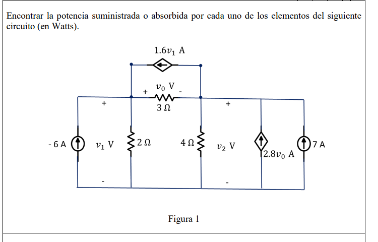
Find the power supplied or absorbed by each of the elements of the following circuit (in Watts).
Encontrar la potencia suministrada o absorbida por cada uno de los elementos del siguiente circuito (en Watts). 1.6V, A Vo V + + 312 - 6 A VV 212 4.12 V2 V Φ7A 2.8v, A Figura 11 answer -
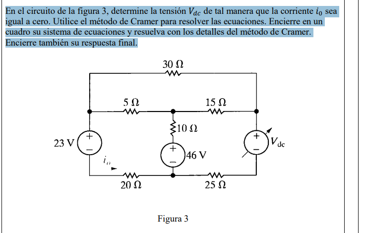
In the circuit of Figure 3, determine the voltage 𝑉𝑑𝑐 such that the current 𝑖0 is equal to zero. Use Cramer's method to solve the equations. enclose in a Table your system of equations and
En el circuito de la figura 3, determine la tensión Vac de tal manera que la corriente io igual a cero. Utilice el método de Cramer para resolver las ecuaciones. Encierre en un cuadro su sistema de1 answer -
Determine the Thévenin equivalents of the circuit shown in Figure 4. What would be the suggested load resistance (impedance) for maximum power transfer? Calculate the power into the load resistor wit
Determine los equivalentes de Thévenin del circuito mostrado en la figura 4. ¿Cuál sería la resistencia (impedancia) de carga sugerida para la transferencia máxima de potencia? Calcule la potenci1 answer -
Find the power supplied or absorbed by each of the elements of the following circuit (in Watts).
Encontrar la potencia suministrada o absorbida por cada uno de los elementos del siguiente circuito (en Watts). 1.6V, A vo V 312 -6A v v 212 412 V2 V A (2.8νο Α Figura 11 answer -
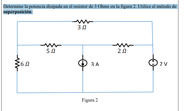
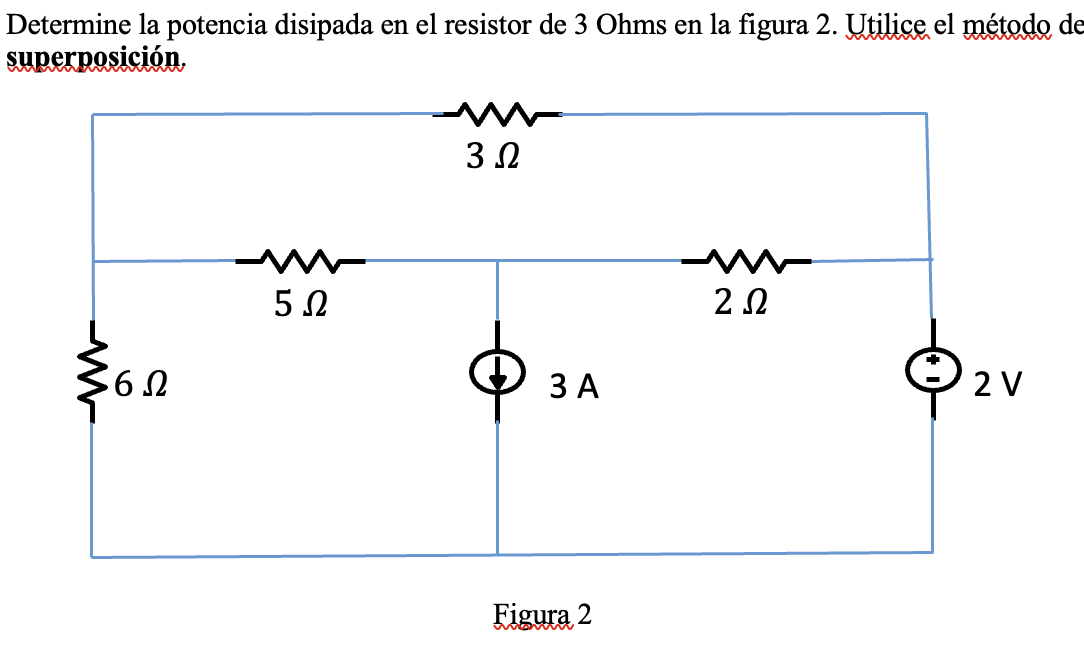
Determine the power dissipated in the 3 Ohm resistor in Figure 2. Use the method of superposition.
Determine la potencia disipada en el resistor de 3 Ohms en la figura 2. Utilice el método de superposición. 3 Ω 5 Ω 2 Ω -- 6 Ω 3Α 2ν Figura 21 answer -
In the circuit of Figure 3, determine the voltage 𝑉𝑑𝑐 such that the current 𝑖0 is equal to zero. Use Cramer's method to solve the equations. enclose in a Table your system of equations and
En el circuito de la figura 3, determine la tensión Vac de tal manera que la corriente i, sea igual a cero. Utilice el método de Cramer para resolver las ecuaciones. Encierre en un cuadro su sistema1 answer -
1 answer
-
1 answer
-
1 answer
-
Impedance of the circuit
2. [20 puntos] En relación con el circuito de la figura, si w = 1x10° rad/s, la impedancia de entrada, Zen es: 50 92 2 mH + 0 Len 2u 1 uF1 answer -
Vo in polar form
= = = 3. [20 puntos] Considerando el circuito de abajo, con los siguientes valores de fasores e impedancias para cada elemento dado: V1 = 20 Z 180° V, V2 = 10 2 0° V, R1 = 20N, R2 1512, C = -j101. E1 answer -
io(t) of the circuit
4. [20 puntos] Obtenga el valor de io(t) en el circuito de la siguiente figura. i 2 k22 2 uF ww + 25 cos(4 x 10³t) V +1 0.25 H 10i, Resultado io(t) en y su unidad:1 answer -
voltage of the circuit
5. [20 puntos] Encuentre el valor del voltaje vo(t) del circuito de la siguiente figura: TF - 422 W 4H + 16 sen 41 V 212 2 cos 4t A WW 6921 answer -
Find Vo in polar form
cada elemento dado: V2 = 20 Z 180° V, V2 = 10 2 0°V, R2 = 201, R2 = 151, C = -j101. Encontrar V, en forma polar. R1 R2 M M TE V. Vi C V21 answer -
1 answer
-
The current entering the positive terminal of a device varies with time as shown in Figure 1. The current is zero at 12 ms and 18 ms. What total amount of charge will have passed through the device in
Pregunta 1: La corriente que entra por la terminal positiva de un dispositivo varía con el tiempo como se muestra en la Figura 1. La corriente es cero en 12 ms y 18 ms. ¿Qué cantidad total de carga1 answer -
1 answer
-
A dc-dc converter is a device that takes a dc voltage as input. unregulated and provides a regulated dc voltage as output. the voltage of output can be lower (buck converter), higher (boost converter)
di 1) Un convertidor dc-dc es un dispositivo que toma como entrada un voltaje de dc no regulado y proporciona un voltaje de dc regulado como salida. El voltaje de salida puede ser más bajo (convertid1 answer -
1 answer
![32e -20° 20 + (6+j8)(4+j2) -10+24j a) Resultado: 2 (19+]20)° (10 +j5)(16– j20) - ) b) 3+j4 Resultado: 1 €) (@ 1 62 – j V900 c](https://media.cheggcdn.com/media/f5e/f5ea347a-9266-49f6-be3d-ad08ffd65d63/phpb9tNmW)
![2. [20 puntos] En relación con el circuito de la figura, si w = 1x10rad/s, la impedancia de entrada, Zen es: 50 Ω 2 mH mo + V](https://media.cheggcdn.com/media/714/7149c546-c926-411b-ae1e-4140cc4b7209/php6Ymely)