¡Tu solución está lista!
Nuestra ayuda de expertos desglosó tu problema en una solución confiable y fácil de entender.
Mira la respuestaMira la respuesta done loadingPregunta: Draw the schematic diagram of a level detector. Consider that the sensor outputs a voltage between -40 mV and 80 mV. Consider that you have a reference voltage Vref = 2.5 V and that it is
Draw the schematic diagram of a level detector.
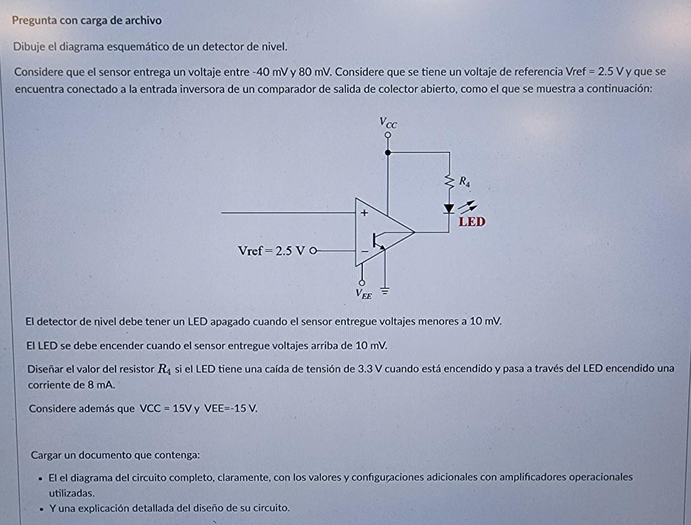
Consider that the sensor outputs a voltage between -40 mV and 80 mV. Consider that you have a reference voltage Vref = 2.5 V and that it is connected to the inverting input of an open collector output comparator, like the one shown below:
The level detector must have an off LED when the sensor delivers voltages less than 10 mV.
The LED should light when the sensor delivers voltages above 10 mV.
Design resistor value
if the LED has a voltage drop of 3.3 V when it is on and a current of 8 mA passes through the lit LED.Also consider that VCC = 15V and VEE=-15V.
Upload a document containing:
The complete circuit diagram, clearly, with additional values and configurations with op amps used.
And a detailed explanation of your circuit design. Intenta enfocarte en un paso a la vez. ¡Tú puedes!SoluciónPaso 1Mira la respuesta completa
Dibujo esquemático del sensor de nivel
 Paso 2
 DesbloqueaPaso 3DesbloqueaPaso 4DesbloqueaPaso 5DesbloqueaPaso 6DesbloqueaRespuestaDesbloquea

Estudia mejor, ¡ahora en español!
Entiende todos los problemas con explicaciones al instante y pasos fáciles de aprender de la mano de expertos reales.