Civil Engineering Archive: Questions from May 20, 2022
-
0 answers
-
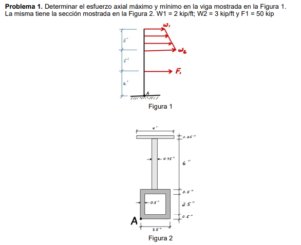
Determine the maximum and minimum axial stress in the beam shown in Figure 1. It has the section shown in Figure 2. W1 = 2 kip/ft; W2 = 3 kip/ft and F1 = 50 kip
Problema 1. Determinar el esfuerzo axial máximo y mínimo en la viga mostrada en la Figura 1. La misma tiene la sección mostrada en la Figura 2. W1 = 2 kip/ft; W2 = 3 kip/ft y F1 = 50 kip W₁ THEMO1 answer -
1 answer
-
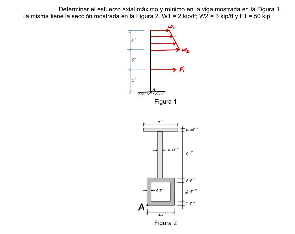
Determine the maximum and minimum axial stress in the beam shown in Figure 1. It has the section shown in Figure 2. W1 = 2 kip/ft; W2 = 3 kip/ft and F1 = 50 kip F₁
Problema 1. Determinar el esfuerzo axial máximo y mínimo en la viga mostrada en la Figura 1. La misma tiene la sección mostrada en la Figura 2. W1 = 2 kip/ft; W2 = 3 kip/ft y F1 = 50 kip F₁ Te TH1 answer -
Problem 1. Determine the maximum and minimum axial stress in the beam shown in Figure 1. It has the section shown in Figure 2. W1 = 2 kip/ft; W2 = 3 kip/ft and F1 = 50 kip Problem 2. Determine the max
Problema 1. Determinar el esfuerzo axial máximo y mínimo en la viga mostrada en la Figura 1. La misma tiene la sección mostrada en la Figura 2. W1 = 2 kip/ft; W2 = 3 kip/ft y F1 = 50 kip F₁ THE S1 answer -
1. Determine the maximum and minimum axial stress in the beam shown in Figure 1. It has the section shown in Figure 2. W1 = 2 kip/ft; W2 = 3 kip/ft and F1 = 50 kip F₁ 2. Determine the maximum shear
Problema 1. Determinar el esfuerzo axial máximo y mínimo en la viga mostrada en la Figura 1. La misma tiene la sección mostrada en la Figura 2. W1 = 2 kip/ft; W2 = 3 kip/ft y F1 = 50 kip F₁ THE A1 answer -
1 answer
-
0 answers
-
Problem 3. Design the most economical W section for the beam shown in Figure 1, using the table provided, an axial yield stress of 52 Ksi and a Safety Factor of 1.17. Consider the self weight of the b
Problema 3. Diseñar la sección W más económica para la viga mostrada en la Figura 1, usando la tabla provista en la Figura 3, un esfuerzo axial de cedencia de 52 Ksi y un Factor de Seguridad de 1.0 answers -
Design the most economical section W for the beam shown in Figure 1, using the table provided in Figure 3, an axial yield stress of 52 Ksi and a Safety Factor from 1.17. Consider the self weight of th
Problema 3. Diseñar la sección W más económica para la viga mostrada en la Figura 1, usando la tabla provista en la Figura 3, un esfuerzo axial de cedencia de 52 Ksi y un Factor de Seguridad de 1.0 answers -
Design the most economical W section for the beam shown in Figure 1, using the table provided in Figure 3, an axial yield stress of 52 Ksi and a Safety Factor of 1.17. Consider the self weight of the
Problema 3. Diseñar la sección W más económica para la viga mostrada en la Figura 1, usando la tabla provista en la Figura 3, un esfuerzo axial de cedencia de 52 Ksi y un Factor de Seguridad de 1.1 answer -
Determine the maximum and minimum axial stress in the beam shown in Figure 1. It has the section shown in Figure 2. W1 = 2 kip/ft; W2 = 3 kip/ft and F1 = 50 kip
Problema 1. Determinar el esfuerzo axial máximo y mínimo en la viga mostrada en la Figura 1. La misma tiene la sección mostrada en la Figura 2. W1 = 2 kip/ft; W2 = 3 kip/ft y F1 = 50 kip W₂ CONFI1 answer -
Problem 3. Design the most economical W section for the beam shown in Figure 1, using the table provided in Figure 3, an axial yield stress of 52 Ksi and a Safety Factor from 1.17. Consider the self w
Problema 3. Diseñar la sección W más económica para la viga mostrada en la Figura 1, usando la tabla provista en la Figura 3, un esfuerzo axial de cedencia de 52 Ksi y un Factor de Seguridad de 1.0 answers -
Determine the maximum and minimum axial stress in the beam shown in Figure 1. It has the section shown in Figure 2. W1 = 2 kip/ft; W2 = 3 kip/ft and F1 = 50 kip
Determinar el esfuerzo axial máximo y mínimo en la viga mostrada en la Figura 1. La misma tiene la sección mostrada en la Figura 2. W1 = 2 kip/ft; W2 = 3 kip/ft y F1 = 50 kip S' F₁ '5' THE SH A F1 answer -
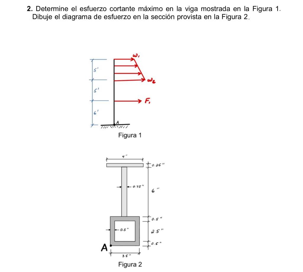
Determine the maximum shear stress in the beam shown in Figure 1. Draw the stress diagram at the section provided in Figure 2
2. Determine el esfuerzo cortante máximo en la viga mostrada en la Figura 1. Dibuje el diagrama de esfuerzo en la sección provista en la Figura 2. 5' W₂ 5' A Figura 1 0.75" 0.5 3.5" Figura 2 F₁1 answer -
Design the most economical W section for the beam shown in Figure 1, using the table provided in Figure 3, an axial yield stress of 52 Ksi and a Safety Factor of 1.17. Consider the self weight of the
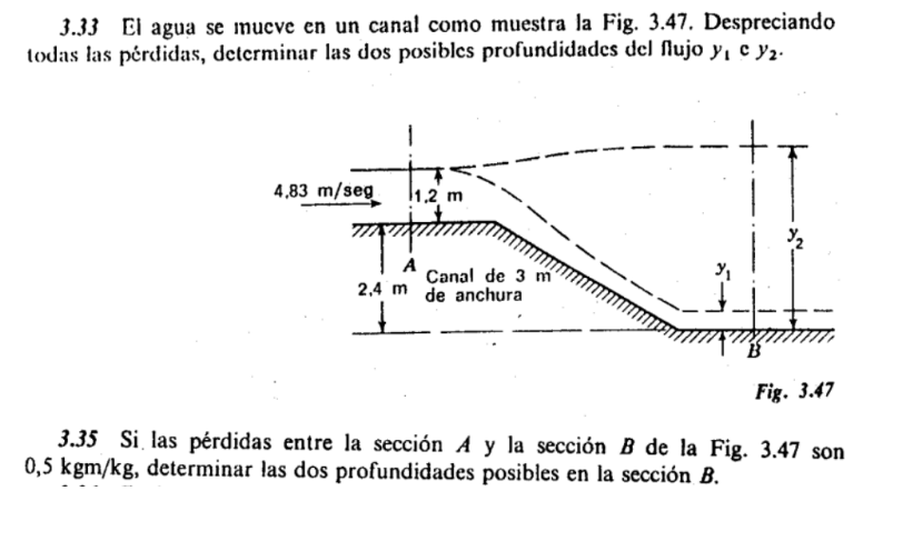
Problema 3. Diseñar la sección W más económica para la viga mostrada en la Figura 1, usando la tabla provista en la Figura 3, un esfuerzo axial de cedencia de 52 Ksi y un Factor de Seguridad de 1.1 answer -
Determine the maximum and minimum axial stress in the beam shown in Figure 1. It has the section shown in Figure 2. W1 = 2 kip/ft; W2 = 3 kip/ft and F1 = 50 kip
Problema 1. Determinar el esfuerzo axial máximo y mínimo en la viga mostrada en la Figura 1. La misma tiene la sección mostrada en la Figura 2. W1 = 2 kip/ft; W2 = 3 kip/ft y F1 = 50 kip W₁ THEMO1 answer -
Determine the maximum and minimum axial stress in the beam shown in Figure 1. It has the section shown in Figure 2. W1 = 2 kip/ft; W2 = 3 kip/ft and F1 = 50 kip
Problema 1. Determinar el esfuerzo axial máximo y mínimo en la viga mostrada en la Figura 1. La misma tiene la sección mostrada en la Figura 2. W1 = 2 kip/ft; W2 = 3 kip/ft y F1 = 50 kip F₁ A Fig1 answer -
For the composite wood beam and the loads shown in the figure, consider section n-n. If it is known that the nails are spaced longitudinally every 50 mm at a and every 25 mm at b. Determine a) the she
1.- Para la viga compuesta de madera y las cargas que se muestran en la figura, considere la sección n-n. Si se sabe que los clavos están espaciados longitudinalmente cada 50 mm en a y cada 25 mm en1 answer -
For simply supported beams and the loads shown in the figures, determine at the center of the beam span a) the equation of the elastic curve of the beam, b) the deflection, c) the slope.
P = 5t Z+ D a M A--> XC 2 m RA 5m L=7m Constante. x EI P = 5t w = 2 t/m Tramo A-C Para el punto D Tramo A - B Para el punto E D RB VDMD RA + MB = 0 -RAL+ Pb=0 RA = Pb L V"punto" (x) VD = RA VERA-P(x-a1 answer -
For simply supported beams and the loads shown in the figures, determine at the center of the beam span a) the equation of the elastic curve of the beam, b) the deflection, c) the slope.
^ 2a a E ✓ A--> XC 2 m VF P RA El P = 5t w = 2 t/m Tramo A C Para el punto E Tramo A D Para el punto F Tramo A B Para el punto G D w b 5 m L=7m Constante. RB VE ME A RA C RA = V"punto" (x) VE = RA V1 answer