¡Tu solución está lista!
Nuestra ayuda de expertos desglosó tu problema en una solución confiable y fácil de entender.
Mira la respuestaMira la respuesta done loadingPregunta: Assemble the circuit of Figure 1 in TINKERCAD, the output of the OPAMP should model the following equation Y = 4X - 2 (Adder -
Assemble the circuit of Figure 1 in TINKERCAD, the output of the OPAMP should model the following equationY = 4X - 2 (Adder - Subtracter).Design criteria:VI= is the load voltage RLV2 = is variable.Bias of the Operational Amplifier V+ = +15 V and V-= -15V.V3, R3, R4, R5, RL at the discretion of the designer.R1, R2, RF1, RF2, RX (if necessary), all these resistances are at the discretion of the designer,looking for the values that meet the expected output from the given equation.The whole circuit operates with direct current (Voltaie DC).for OPAMP output they will have a margin of error between + - 0.8.Example:Y=4x- 7 s X= 2 then cY=6Vout = 4V2 - 2, if V2 = 2 then Vout = 6V. However, the result can be between 6.8 and 5.2They must fill out the following table of results, for the different values of V2Need a photo of the Simulation RUNNING thank you! Esta es la mejor manera de resolver el problema.Solución100% (1 calificación)
TinkerCad Model: For X = 0.5V: For X = 1V: For X = 1.5V: Table: 15.0V 500 mW O 3.26 malO 15.0V 了 A) 250 A 3.30 mA 00 0.00 V 00 00 8.00 V 2.5…
Mira la respuesta completa
Texto de la transcripción de la imagen:
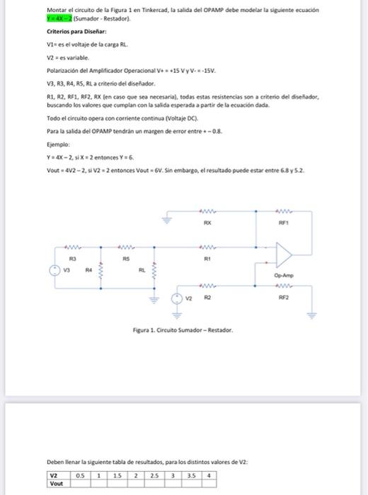
Montar el circuito de la figura 1 en Tinkertad, la salida del OPAMP debe modelar la siguiente ecuación Yaxsumador - Restador) Criterios para Diseñar: Vi-es el voltaje de la carga Rt. V2 es variable Polarización del Amplificador Operacional V+ = +15 VYV--- ISV. V3, R3, R4, RS, RL a criterio del diseñador. RL, R2RFI, RF2, RX (en caso que sea necesarial, todas estas resistencias son a criterio del diseñador. buscando los valores que cumplan con la salida esperada a partir de la ecuación dada. Todo el circuito opera con corriente continua (Voltaje DC). Para la salida del OPAMP tendrán un margen de error entre - 0.8. Ejemplo: Y4X-2, 3X2 entonces Y=6. Vout 402-2.5 V2 -2 entonces Vout - 6v. Sin embargo, el resultado puede estar entre 6.8y52. WW ROX RFI 2 R3 RS R1 s V3 RA 2 2 Op Amp V2 8 RE2 Figura 1. Circuito Sumador - Restador Deben llenar la siguiente tabla de resultados, para los distintos valores de V2: V2 05 1 15 2 25 3 3.5 4 Vout

Estudia mejor, ¡ahora en español!
Entiende todos los problemas con explicaciones al instante y pasos fáciles de aprender de la mano de expertos reales.