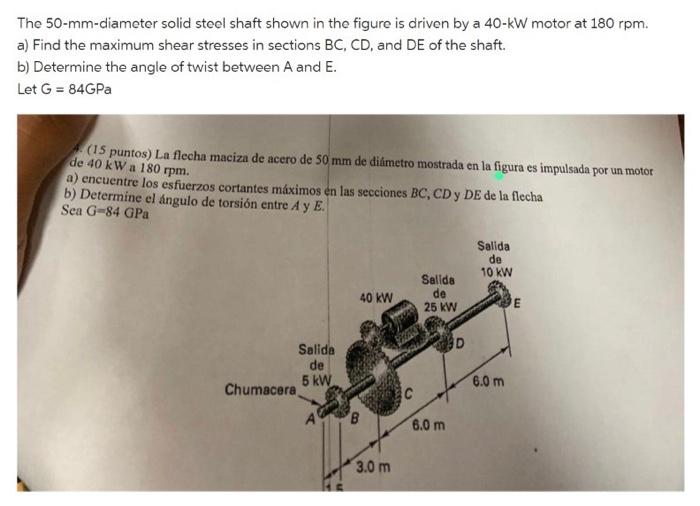
Pregunta: The 50-mm-diameter solid steel shaft shown in the figure is driven by a 40−kW motor at 180rpm. a) Find the maximum shear stresses in sections BC,CD, and DE of the shaft. b) Determine the angle of twist between A and E. Let G=84GPa (15 puntos) La flecha maciza de acero de 50 mm de diámetro mostrada en la figura es impulsada por un motor de 40 kW a 180rpm. a)
 Esta pregunta aún no se resolvió!¿No es lo que buscas?Envía tu pregunta a un experto en la materia.Texto de la transcripción de la imagen:The 50-mm-diameter solid steel shaft shown in the figure is driven by a 40−kW motor at 180rpm. a) Find the maximum shear stresses in sections BC,CD, and DE of the shaft. b) Determine the angle of twist between A and E. Let G=84GPa (15 puntos) La flecha maciza de acero de 50 mm de diámetro mostrada en la figura es impulsada por un motor de 40 kW a 180rpm. a) encuentre los esfuerzos cortantes máximos en las secciones BC,CD y DE de la flecha b) Determine el ángulo de torsión entre A y E. Sea G=84GPa
Texto de la transcripción de la imagen:
The 50-mm-diameter solid steel shaft shown in the figure is driven by a 40−kW motor at 180rpm. a) Find the maximum shear stresses in sections BC,CD, and DE of the shaft. b) Determine the angle of twist between A and E. Let G=84GPa (15 puntos) La flecha maciza de acero de 50 mm de diámetro mostrada en la figura es impulsada por un motor de 40 kW a 180rpm. a) encuentre los esfuerzos cortantes máximos en las secciones BC,CD y DE de la flecha b) Determine el ángulo de torsión entre A y E. Sea G=84GPa

Estudia mejor, ¡ahora en español!
Entiende todos los problemas con explicaciones al instante y pasos fáciles de aprender de la mano de expertos reales.